LM-79 Moving Detector Goniophotometer (Mirror Type C)
LSG-6000

High Precision Rotation Luminaire Goniophotometer
LSG-1890B

High Precision Rotation Luminaire Goniospectroradiometer
LSG-1890BCCD

Goniophotometer for Automotive and Signal Lamps
LSG-1950

Goniophotometer for Traffic Signal Lamps
LSG-1950S

Compact Goniophotometer
LSG-1200A

Near Field Moving Detector Goniophotometer
LSG-1900B


Select an organization
to browse standards
125.1 Grounding receptacles having a 5-15R,5-20R,6-13R,6-20R,7-15R,14-15Ror 15-15R configuration are to be subjected to the tests in this section.
125.2 Previously untested devices are to be used. Each device is to be mounted in a flush device box, or as otherwise intended, with its face in a vertical plane. A nonmetallic faceplate is to be installed if intended. A solid 14 AWG (2.1 mm2) copper conductor is to be connected to the receptacle grounding terminal.
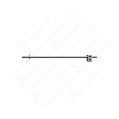
GNGPL SB1610_AL
125.3 With the receptacle oriented to create the maximum contact displacement (possible distortion of contact affecting its contact ability), the test pin A. Figure 125.1 is to be fully inserted in the grounding contact. A 5 lb (2.27 kg) weight is to be gradually suspended form the test pin 6 inches (152 mm) from the face of the receptacle. The weight is to be applied for 1 minute, following which, the weight is to be removed. The application of the weight is to be repeated with the receptacles rotated 90, 180 and 270 degrees for a total of four applications. Usually the test is started with the grounding pin opening directly above, below or on either side of the line slots.
125.4 As a result of the test described in125.3, there shall not be any breakage of the outlet face of the receptacle that would expose live parts to contact by 1/16 inch (1.6 mm) diameter rod. In addition, there shall not be any breakage or distortion of the insulating body of the receptacle that results in reduction of electrical spacings to values less than those required for the receptacle. The conditioning pin shall remain in place without extraneous support for the required 1 minute in each position.
Exception: If breakage occurs at the base of the grounding contact opening in a controlled manner so that the breakage is clean and does not expose live parts or break internal barriers, minimal extraneous support of the conditioning pin is not prohibited to complete the stress conditioning on the grounding contacts.
125.5 Each device is then to be tested for electrical continuity between the receptacle grounding contact and the fully inserted test pin B,Figure 125.2. There shall not be a loss of contact while the pin is moved by hand, without exerting undue pressure, so as to touch all internal walls and surfaces. The stop ring of the pin is to remain continuously in contact with the face of the receptacle. An indicating device, such as an ohmmeter, a battery-and-buzzer combination, or other similar device, is to be used.
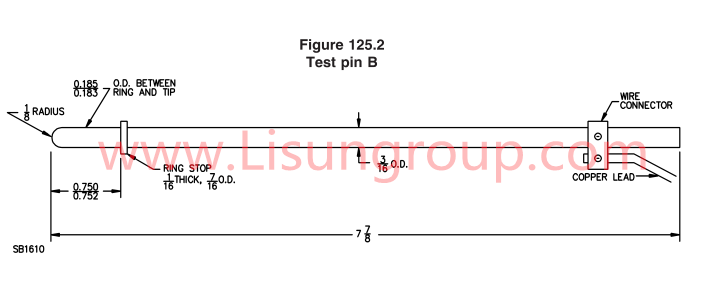
Test Pin B with UL 498 Figure 125.2
125.6 Each device is then to be positioned with the receptacle outlet facing down in a horizontal position. The receptacle shall support the 2 and 4 oz. (57 and 113g) grounding pin illustrated in Figure 125.3 and Figure 125.4, for 1 minute each when fully inserted in the grounding pin opening.
Tags:GNGPL-SB1610 , UL 498Your email address will not be published. Required fields are marked *


 English
 中文简体
中文简体 English
 Русский
 Español
 Português
 Türkçe
 العربية
 Deutsch
 Polski
 Italiano
 Français
 한국어
한국어 ไทย
ไทย Tiếng Việt
 日本語
日本語