LM-79 Moving Detector Goniophotometer (Mirror Type C)
LSG-6000

High Precision Rotation Luminaire Goniophotometer
LSG-1890B

High Precision Rotation Luminaire Goniospectroradiometer
LSG-1890BCCD

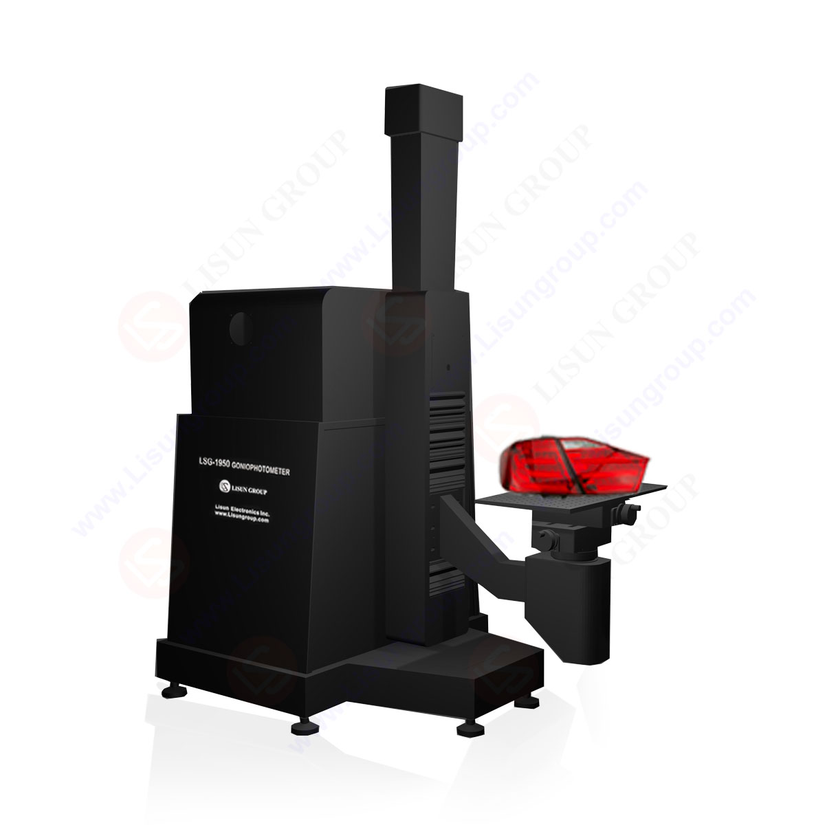
Goniophotometer for Automotive and Signal Lamps
LSG-1950

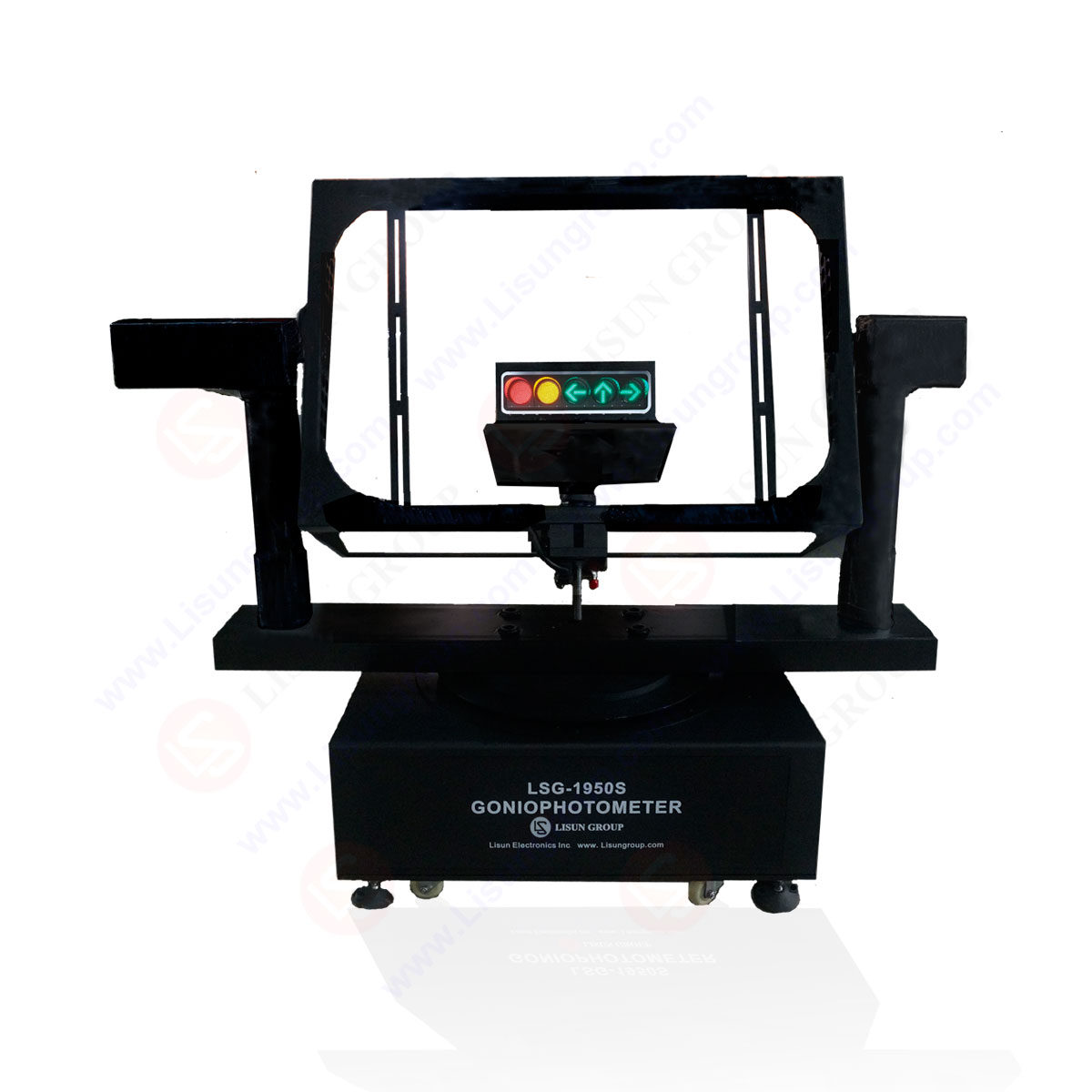
Goniophotometer for Traffic Signal Lamps
LSG-1950S

Compact Goniophotometer
LSG-1200A

Near Field Moving Detector Goniophotometer
LSG-1900B


Select an organization
to browse standards
Low-intensity obstacle light-Characteristics 6.3.23 Low-intensity obstacle lights on fixed objects.
Types A and B, shall be fixed-red lights
6.3.24 Low-intensity obstacle lights, Types A and B, shall be in accordance with the specifications in Table 6-3.
6.3.25 Low-intensity obstacle lights, Type C, displayed on vehicles associated with emergency or security shall be flashing-blue and those displayed on other vehicles shall be flashing-yellow.
6.3.26 Low-intensity obstacle lights. Type D. displayed on follow-me vehicles shall be flashing-yellow.
6.3.27 Low-intensity obstacle lights, Types C and D, shall be in accordance with the specifications in Table 6-3.
6.3.28 Low-intensity obstacle lights on objects with limited mobility such as aerobridges shall be fixed-red. The intensity of the lights shall be sufficient to ensure conspicuity considering the intensity of the adjacent lights and the general levels of illumination against which they would normally be
viewed.
6.3.29 Low-intensity obstacle lights on objects with limited mobility shall as a minimum be in accordance with the specifications for low-intensity obstacle lights. Type A, in Table 6-3.
Medium-intensity obstacle light-Characteristics
6.3.30 Medium-intensity obstacle lights, Type A, shall be flashing-white lights, Type B shall be flashing-red lights and Type C shall be fixed-red lights.
6.3.31 Medium-intensity obstacle lights. Types A. B and C, shall be in accordance with the specifications in Table 6-3.
6.3.32 Medium-intensity obstacle lights. Types A and B. located on an object shall flash simultaneously.
High-intensity obstacle light- Characteristics
6.3.33 High-intensity obstacle lights, Types A and B. shall be flashing-white lights.
6.3.34 High-intensity obstacle lights, Types A and B.shall be in accordance with the specifications in Table 6-3.
6.3.35 High-intensity obstacle lights, Type A, located on an object shall flash simultaneously.
6.3.36 Recommendation.- High-intensity obstacle lights, Type B, indicating the presence of a tower supporting
overhead wires, cables, etc., should flash sequentially; first the middle light, second the top light and last, the bottom light. The intervals between flashes of the lights should approximate the following ratios:
Flash interval between
Ratio of cycle time
middle and top light
1/13
top and bottom light
2/13
bottom and middle light
10/13.
Effective intensity, as determined in accordance with the Aerodrome Design Manual. Part 4.
Beam spread is defined as the angle between two directions in a plane for which the intensity is equal to 50% of the lower tolerance value of the intensity shown in columns 4.5 and 6. The beam pattern is not necessarily symmetrical about the elevation angle at which the peak intensity occurs.
Elevation (vertical) angles are referenced to the horizontal.
Intensity at any specified horizontal radial as a percentage of the actual peak intensity at the same radial when operated at each of the intensities shown in columns 4, 5 and 6.
Intensity at any specified horizontal radial as a percentage of the lower tolerance value of the intensity shown in columns 4, 5 and 6.
In addition to specified values, lights shall have sufficient intensity to ensure conspicuity at elevation angles between ±0 and 50.
Peak intensity should be located at approximately 2.5 vertical.
Peak intensity should be located at approximately 17 vertical. fpm-flashes per minute; N/A-not applicable
LISUN following instruments fully meet ICAO Annex 14 Volume I, Chapter 5 Chapter 6
Your email address will not be published. Required fields are marked *


 English
 中文简体
中文简体 English
 Русский
 Español
 Português
 Türkçe
 العربية
 Deutsch
 Polski
 Italiano
 Français
 한국어
한국어 ไทย
ไทย Tiếng Việt
 日本語
日本語