LM-79 Moving Detector Goniophotometer (Mirror Type C)
LSG-6000

High Precision Rotation Luminaire Goniophotometer
LSG-1890B

High Precision Rotation Luminaire Goniospectroradiometer
LSG-1890BCCD

Goniophotometer for Automotive and Signal Lamps
LSG-1950

Goniophotometer for Traffic Signal Lamps
LSG-1950S

Compact Goniophotometer
LSG-1200A

Near Field Moving Detector Goniophotometer
LSG-1900B


Select an organization
to browse standards

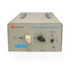
Product No: LISN-PVDC8301
The symmetrical DC artificial power supply network LISN-PVDC8301, in conjunction with the LISUN EMI-9KB or EMI-9KA receiver, can be used to measure the disturbance voltage in the frequency range of 0.15 MHz to 30 MHz for photovoltaic inverters. The LISN-PVDC8301 is designed according to CISPR 16-1-2 to measure the conducted emissions of photovoltaic inverters at the power terminal. The circuit concept of photovoltaic inverters may generate ripple currents on the DC side of the inverter, which are mostly proportional to the power frequency. These ripple currents can be transmitted through cables and photovoltaic generator modules, and can act as magnetic field radiation, sometimes causing significant interference effects. Conventional measurements at the AC terminals of photovoltaic inverters cannot reveal such interference phenomena. LISN-PVDC8301 is especially designed to measure all kinds of disturbance voltages at the DC-side of photovoltaic inverters. These are in detail the disturbance voltage of one conductor above reference ground (unsymmetrical disturbance voltage), the common mode disturbance voltage of a pair of conductors above ground (asymmetrical disturbance voltage) and finally, the differential mode voltage between two conductors.
Specification:
| Frequency Range | 0.15 MHz – 30 MHz |
| Max Current (DC) | 200 A |
| Max Voltage (DC) | 1500 V |
| Common Mode Impedance | (150 +/- 30) Ω |
| (Mode switch CM, A or B) | |
| Differential Mode Impedance | (150 +/- 30) Ω |
| (Mode switch DM) | |
| Phase at EUT-Terminals | (0 +/- 40)° |
| Insertion loss (EUT – AE) | >20 dB |
| Longitudinal conversion loss LCL | >26 dB |
| Voltage Division Factor at the measuring port | typ. (20 +/- 3) dB (10:1) |
| Resistance (DC) with feed terminals shorted (T=25°C) | <50 mΩ |
| EUT Connectors | M12 terminals with banner socket |
| Dimensions | 42*28*44 cm |
| Weight | approx. 33 kg |
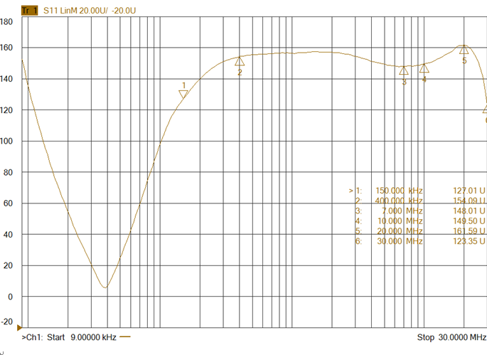
Figure 1 Common Mode Impedance
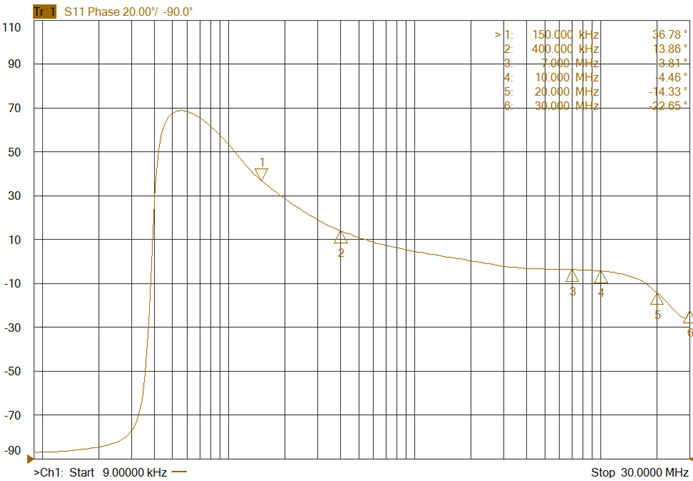
Figure 2 Common mode phase diagram
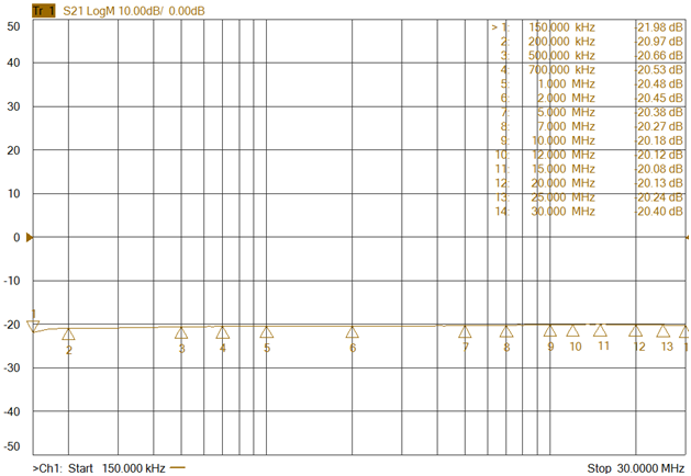
Figure 3: C-end (common mode) attenuation coefficient diagram
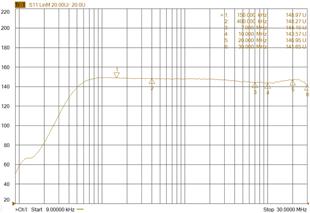
Figure 4: D-end (differential mode) impedance diagram
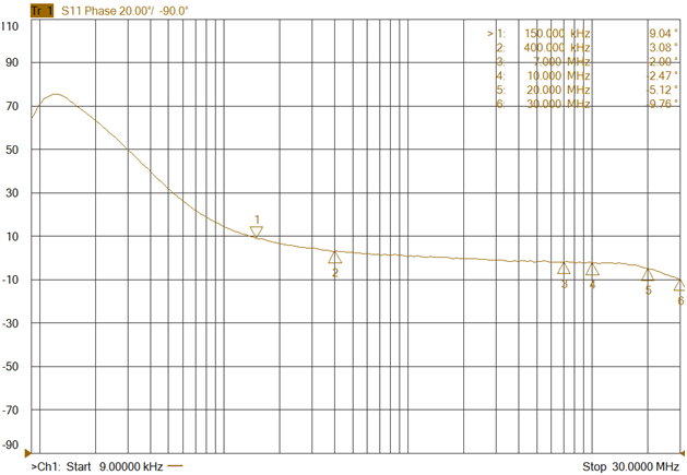
Figure 5: D-end (differential mode) phase diagram
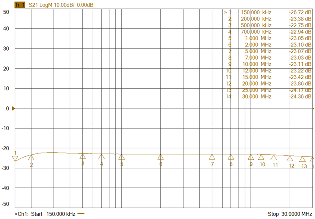
Figure 6: D-end (differential mode) attenuation coefficient diagram
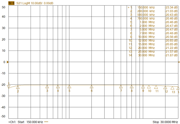
Figure 7: A-end attenuation coefficient diagram
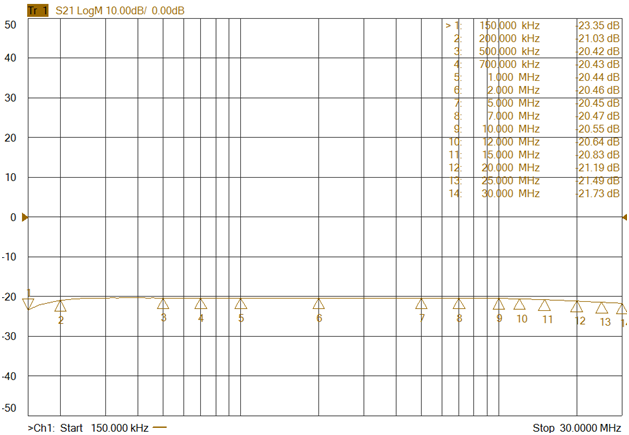
Figure 8: B-end attenuation coefficient diagram
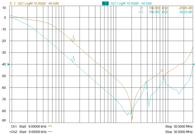
Figure 9: B-end attenuation coefficient diagram


 English
 中文简体
中文简体 English
 Русский
 Español
 Português
 Türkçe
 العربية
 Deutsch
 Polski
 Italiano
 Français
 한국어
한국어 ไทย
ไทย Tiếng Việt
 日本語
日本語