LM-79 Moving Detector Goniophotometer (Mirror Type C)
LSG-6000

High Precision Rotation Luminaire Goniophotometer
LSG-1890B

High Precision Rotation Luminaire Goniospectroradiometer
LSG-1890BCCD

Goniophotometer for Automotive and Signal Lamps
LSG-1950

Goniophotometer for Traffic Signal Lamps
LSG-1950S

Compact Goniophotometer
LSG-1200A

Near Field Moving Detector Goniophotometer
LSG-1900B


Select an organization
to browse standards
A flush or self-contained receptacle having a 5-15R,5-20R,6-15R, or 6-20R configuration shall be subjected to the retention of blades test described in this Section.
Exception: A receptacle having a 1-15R,5-15R,5-20R,6-15R, or 6-20R configuration and not of the flush or self-contained type may instead be subjected to the Retention of Plugs Test, Section 116.
Receptacles having the break-off tab, when provided, removed from one nonidentified terminal are to be subjected to ten conditioning cycles of manual insertion and withdrawal of a standard test gauge, see Figure 111.1. Each of six devices is to be tested. The gauge is to be configured as outlined in Table 111.1. The force applied to insert the gauge for any of the conditioning cycles is not to exceed 40 lbf (178 N). The gauge is to have the dimensions indicated in Figure 111.1 but is not to have holes in the outer ends of the blades.
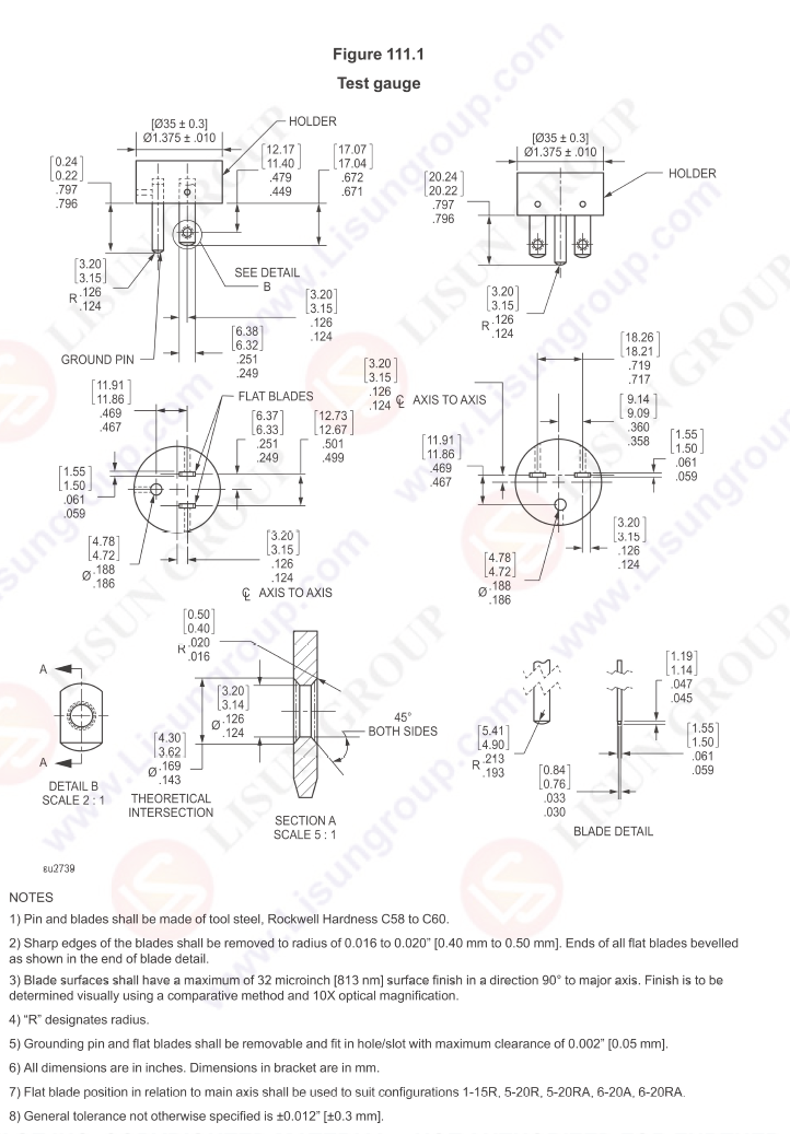
Test Gauge with UL498 Figure 111.1
The standard test gauge is to be configured as shown in Table 111.2 using the line blades without holes and with the grounding blade removed. The gauge is then to be inserted in the receptacle and a static 3 lbf (13.3 N) (including the weight of the gauge), which tends to remove the gauge from the receptacle, is to be applied for a period of 1 minute in a direction normal to the plane of the face of the receptacle. There shall not be more than 0.079 inch (2 mm) displacement of the gauge.
The standard gauge is to be configured as shown in Table 111.3 using the line blades with holes in the end and with the grounding blade in place. The test is to be conducted using the apparatus as described in Figure111.1A. The test gauge is attached to the apparatus as shown. The apparatus consists of a principal mass, and a supplementary mass. The supplementary mass is 1.5 lbs (6.7 N). The principal mass, together with the supplementary mass, the Gage and any hardware equals 15 lbs (67 N) total. The gage is inserted fully into the device.
The principal mass and associated hardware is hung on the gage without jolting. The gage shall not remain in the receptacle. If the gage does not withdraw the supplementary mass is raised and allowed to fall from a height of 2 in (51 mm) onto the principal mass one time. The gage shall not remain in the receptacle. A test apparatus that does not incorporate a supplementary mass and equals the 15 lbs (67 N) total is permitted if agreeable to all parties.
Tags:GNGPL-SU2739Your email address will not be published. Required fields are marked *


 English
 中文简体
中文简体 English
 Русский
 Español
 Português
 Türkçe
 العربية
 Deutsch
 Polski
 Italiano
 Français
 한국어
한국어 ไทย
ไทย Tiếng Việt
 日本語
日本語