LM-79 Moving Detector Goniophotometer (Mirror Type C)
LSG-6000

High Precision Rotation Luminaire Goniophotometer
LSG-1890B

High Precision Rotation Luminaire Goniospectroradiometer
LSG-1890BCCD

Goniophotometer for Automotive and Signal Lamps
LSG-1950

Goniophotometer for Traffic Signal Lamps
LSG-1950S

Compact Goniophotometer
LSG-1200A

Near Field Moving Detector Goniophotometer
LSG-1900B


Select an organization
to browse standards
40a. The gauges illustrated in figures 2, 3, 4 and 5 in BS546 shall be considered to comply with the dimensional requirements if the results of the measured values are within the specified dimensions and the uncertainty of measurement at not less than 95% confidence level does not exceed ±0.0002in/0.005mm.
41.‘Go’gauge for plug (see Fig. 3 and Table 20). The gauge is to prove correct spacing of plug-pins. It accepts the plugs with plug-pins at any centres that can be accepted without interference in sockct-outlets gauged by the maximum and minimum socket-gauges.
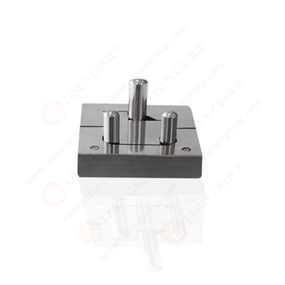
GNGPL 5405_AL
In addition it proves the absence of axial “projections on the face of the plug-base when a plug is fully inserted into the gauge, and it also indicates accuracy of projection of the plug-pins from the face of the plug if the end of cach plug-pin lies within the appropriate step on the back of the gauge when the plug is fully inserted.
NOTE. Correctness of the diameter of individual plug-pins in accordance with Clause 15, Table 7 must be assured before this gauge is used. ‘Go’gauges for socket-outlet (see Figure 4 and Figure 5 and Tables 21 and 22). Two gauges are required, each having pins of the maximum diameters specified in Clause 15, but one gauge having its pins so set that its complete insertion into a socket-outlet proves that the socket-outlet will accept, without interference, a plug having plug-pins at the maximum centre distance and the other gauge having its pins so set that its complete insertion into a socket-outlet proves that the socket-outlet will accept without interference a plug having plug-pins at the minimum centre distance. The socket-outlet gauges also prove the absence of axial pro-jections on the face of the socket-outlet.

Minimum GO Gauge for Socket-Outlet of BS 546 Figure 5
Withdrawal-pull gauges for effectiveness of contact (see Figs. 2). These gauges are to test the withdrawal-pull specified in Clause 33, and shall be used in individual socket-contacts of complete socket-outlets. They shall be applied, when used, after the maximum ‘ Go ’gauge for socket-outlet.
When gauging line and neutral socket-contacts, the shutter, if any, shall be kept clear of the gauge.
Your email address will not be published. Required fields are marked *


 English
 中文简体
中文简体 English
 Русский
 Español
 Português
 Türkçe
 العربية
 Deutsch
 Polski
 Italiano
 Français
 한국어
한국어 ไทย
ไทย Tiếng Việt
 日本語
日本語